7.1 - Introduction to Cameras
We would like to move around a virtual scene and view it from various vantage points, just as you would using a real world camera. In the real world a scene remains stationary while a person takes pictures by moving to various vantage points. But it turns out that in a virtual world it is more mathematically efficient to keep the camera stationary and move the scene in front of the camera. And it turns out that we can move the entire scene in front of the camera quite easily.
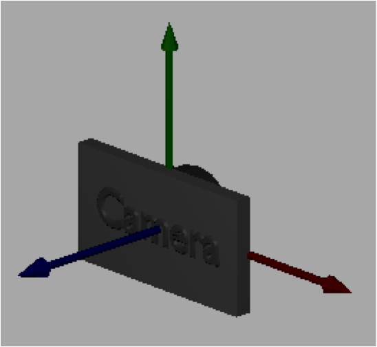
Our virtual camera will be located at the global origin and oriented to look down the -Z axis, with the Y axis pointing up and the X axis pointing to the camera’s right. The camera will always be in this position and orientation. Our discussion of cameras focuses on how to get a desired view of a scene in front of a stationary camera.
Camera Motion vs. Scene Motion
A person uses the relationship between the foreground and background to unconsciously determine whether they are moving or the objects around them are moving. Pretend that your eye is the camera and that you are traveling in a car. Objects close to you, like a building along the road, move quickly through your field of view and the landscape in the distance also moves, but more slowly. The fact that both the close objects and the distant objects are moving is your visual cue that the camera (which is you) is moving. If you stop your car and watch the other cars go by, what changes is that the background becomes completely stationary. The difference in movement between the foreground and the background allows your mind to discern whether you are moving or stationary. For this reason when we move a scene in front of a camera it is important that everything in the scene, including the background, be moved.
Animations are created by changing the location and orientation of objects in a scene over time, or by changing the location and orientation of the camera that is viewing the scene, or by moving both the objects and the camera. If you hold the objects stationary and move the camera, the motion required is opposite of that required if you hold the camera stationary and move the objects. For example, consider an object that you want to move from left to right in front of a camera. If the camera is in the default position and orientation looking down the -Z axis, the object needs to be translated alone the X axis from say -5 to +5. However, that same motion could be produced by moving the camera from right to left, say from +5 to -5. If there is nothing in the background, it would be impossible to know whether the camera or the object was moving, or if both were moving. Therefore, be aware that the motion of objects and the motion of a camera are opposites for visually identical motions. So when you move objects around in a scene, you think in terms of the object’s coordinate system. But when you move the camera, you need to think in terms of the camera’s coordinate system.
A Camera Definition
To define a camera we need a position and an orientation. We typically call the position of the camera the “eye” position and we define its location using a global point (eye_x, eye_y, eye_z). The orientation of a camera is best defined by three orthogonal axes that define a local, right-handed coordinate system. To keep these axes separate from the global x, y and z coordinate axes, let’s use the names u, v, and n. (The names are arbitrary and you will find different notations for the camera axes as you search the web.) If a camera is located at the origin looking down the -Z axis, then u would align with the x axis, v would align with the y axis, and n would align with the z axis. This is summarized in the following notation, where the symbol - -> means “maps to”.
u --> x
v --> y
n --> z
We can specify a camera using the 12 values shown below, which define one global point and three vectors.
eye = (eye_x, eye_y, eye_z)  // the location of the camera
u = <ux, uy, uz>             // points to the right of the camera
v = <vx, vy, vz>             // points up from the camera
n = <nx, ny, nz>             // points backwards; -n is the center of view
The values must define each camera axis such that it has a 90-degree angle to the other two axes and the axes form a right-handed coordinate system. Mathematically, the following must be true for a valid, right-handed camera coordinate system. To simplify the math, we always store the axes as unit vectors. Remember that the order of vectors in a cross product matters. If you were to switch the order of the vectors below, you would not get the correct results.
dot_product(u,v) === 0    // cos(90) == 0
dot_product(v,n) === 0    // cos(90) == 0
dot_product(n,u) === 0    // cos(90) == 0
cross_product(u,v) === n
cross_product(v,n) === u
cross_product(n,u) === v
Specifying a Virtual Camera
It is difficult for programmers to define a camera orientation using three normalized vectors that designate a right-handed coordinate system. Therefore, we typically define a camera in more natural terms and let the computer calculate the camera coordinate system. A straightforward description of a camera can be achieved using two points and a single vector like this:
- Specify the location of the camera.
- This actually gives us two values – the eye location and a reference point to form the camera’s coordinate system axes.
- Specify a location the camera is looking at.
- This value can be any point that is in front of the camera along it’s line-of-sight. It’s exact location along the line-of-sight does not matter. This point defines the direction of the -n axis. Since we normalize the coordinate system axes to unit length, the direction of this vector is the only thing we care about.
- It is your responsibility as the programmer to make sure that this point and the eye location form a vector. If the two points are at the same location, the -n axis will not be a valid vector and the lookAt() function will fail to create a valid camera coordinate system.
- Specify the general direction of “up” for the camera.
- This vector does not have to be precise. The typical value is <0,1,0>, which is pointing in the Y axis direction.
- The cross product of this vector and the negation of the line-of-sight vector will produce the u axis of the camera’s coordinate system.
- If the “up” vector is exactly along the camera’s line of sight, the cross product calculation will fail and the camera coordinate system will not be valid. It is your responsibility as the programmer to make sure the line-of-sight vector and the “up vector” do not point in the same direction.
- The last axis of the camera’s coordinate system, v, which points directly “up” from the camera is calculated by taking the cross product of the u and n vectors.
Based on these ideas, the Javascript Learn_webgl_matrix class contains the following function:
/** -----------------------------------------------------------------
 * Set a camera matrix.
 * @param M Float32Array The matrix to contain the camera transformation.
 * @param eye_x Number The x component of the eye point.
 * @param eye_y Number The y component of the eye point.
 * @param eye_z Number The z component of the eye point.
 * @param center_x Number The x component of a point being looked at.
 * @param center_y Number The y component of a point being looked at.
 * @param center_z Number The z component of a point being looked at.
 * @param up_dx Number The x component of a vector in the up direction.
 * @param up_dy Number The y component of a vector in the up direction.
 * @param up_dz Number The z component of a vector in the up direction.
 */
self.lookAt = function (M, eye_x, eye_y, eye_z, center_x, center_y, center_z, up_dx, up_dy, up_dz) {
The following demonstration allows you to change these parameters and immediately see the results. Experiment with the parameters until you are comfortable with how they change the camera view.
Manipulate the parameters of a lookAt() created virtual camera. Note:
- The eye location is at the center of the camera
- The center location starts at the origin, which is also the center of the widget. The center location is visible if you move it away from the origin. Note how the camera is always pointed at this location.
- The "up" vector is drawn as a black line segment.
- Mouse drags will allow you to get different views of the left canvas window.
- The scenes are rendered in perspective mode so you can sense depth.
Manipulate the function lookAt(M, eye_x, eye_y, eye_z, center_x, center_y, center_z, up_dx, up_dy, up_dz)
| eye (0.0, 0.0, 5.0) | center (0.0, 0.0, 0.0) | up <0.0, 1.0, 0.0> |
| X: -5.0 +5.0 | X: -5.0 +5.0 | X: -1.0 +1.0 |
| Y: -5.0 +5.0 | Y: -5.0 +5.0 | Y: -1.0 +1.0 |
| Z: -5.0 +5.0 | Z: -5.0 +5.0 | Z: -1.0 +1.0 |
Open this webgl program in a new tab or window
Camera Errors
An invalid camera definition will produce unpredictable rendering output. We have already discussed the conditions that will create errors in a camera, but it is very important that you include tests in your code to avoid these potential errors. A camera calculated using the lookat() function will be invalid if:
- The “eye” and “center” point are the same location.
- The “up vector” has the same direction as the line-of-sight (which is a vector between the “eye” and the “center” point). For this case, the “same direction” includes both positive and negative directions. Stated mathematically, if the sine of the angle between the “up vector” and the line-of-sight vector is zero, which happens if the angle between the vectors is 0 or 180, the camera definition will fail.
Glossary
- virtual camera
- Defines a position and orientation from which to view a scene.
- camera coordinate system
- Three orthogonal axes that form a right-handed coordinate system. Each axis is defined as a vector in global coordinates.
- eye
- The 3D location of a camera defined in global coordinates.
- camera center point
- The 3D location that a camera is pointed towards. This point will always be rendered exactly in the center of the output image.
- camera up vector
- A 3D vector that points in the general direction of “up” from the camera. The exact direction of “up” for the camera is calculated from the u and n vectors.