3.4 - Volume / Surfaces
We have discussed location and direction. Now we need to discuss how to represent 3-dimensional shapes and the area they occupy in space. An object might be a cube, a sphere, a plane, or a complex blob. Objects take on an infinite variety of forms. It is certainly possible to describe each object in a unique way, but that would require a unique rendering algorithm for each object. What we would like is a uniform way to describe any type of object regardless of the complexity of its form. You may be surprised, but almost all rendering algorithms only know how to render triangles!
Why only triangles?
- A triangle is the simplest geometric shape that defines an enclosed area. Triangles have an inside area and an outside area.
- A triangle is always planar – it always defines a flat surface.
- A triangle divides 3-dimensional space into three distinct regions. All points in 3-dimensional space lie 1) in the plane defined by the triangle, 2) on one side of the plane or 3) on the other side of the plane. Think of a triangle as defining a piece of flat paper. By convention we can say one side of a triangle is the front side and the other side the back side. By combining triangles we can create shapes that have an inside and an outside.
- A triangle is always convex; it is impossible for a triangle to be concave. Rendering concave polygons is harder than rendering convex polygons.
These properties make the rendering of triangles straightforward and fast, which makes 3D real-time graphics possible!
Defining Triangles
Triangles are defined using location and direction values we defined in the previous lessons.
Any 3 points (locations) in space define a triangle – as long as the 3 points do not lie on top of each other or along a line. You might think that 3 points on top of each other or along a line would be rare, but as you manipulate 3D objects these conditions can happen often. Therefore, as you develop computer graphics software you must continually test for such cases. Three points that do not define a valid triangle are called a “degenerate case”. Degenerate cases are problematic because they do not define an enclosed area or divide 3D space into 3 regions. But perhaps more importantly, degenerate cases cause the mathematics that manipulates the triangles to fail. To summarize,
- A triangle is defined by three points (locations).
- Degenerate cases:
- The three points are not distinct. (Two or three of them are identical.)
- The three points lie along a line.
The three points of a triangle define three edges or boundary line segments. The three points are the locations where the boundary line segments intersect. The intersection point of two geometric objects is called a vertex. Modeling software refers to the points that define a triangle as vertices.
A triangle has two sides: a front side and a back side. The surface of a triangle that is enclosed within its edges are often referred to as a triangle’s face. (Notice that “face” is a kind of abbreviation for sur”face”.) A triangle has two faces. A viewer can only see one face at a time. The front face is visible to a viewer if the viewer is on the front side of the triangle. Similarly, the back face is only visible to a viewer if the viewer is on the back side of the triangle. This is important because in a scene with a single light source only one side of the triangle will get light. In addition, only one side of a triangle can be facing the scene’s camera. For triangles that are part of a larger object, the orientation of the face can be used to determine if the face is visible to the camera.
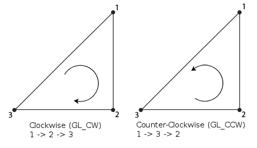
Winding Order for a triangle.
The order of a triangle’s vertices are used to determine which side of a triangle is the front side. If you are looking at a triangle and the order of the vertices is counter-clockwise, then, by convention, you are looking at the front of the triangle. The order of a triangle’s vertices is called the winding order. There are two possible windings, as shown in the image below (1). If a triangle is not being drawn as you expect, it could be because the winding order of its vertices is backwards.
A flat triangle has two important vectors associated with it. Both vectors are at right angles to every point inside the triangle. One vector points away from the front face; the other vector points away from the back face. These vectors can be seen in the image below. (2) You can calculate these vectors by taking the vector cross-product of any two edges of the triangle. Which edges you use and the order you perform the cross-product determines which vector you calculate. If a triangle’s vertices have a counter-clockwise winding order, and we take the cross product of edge 1 (between vertices 1 and 2) and edge 2 (between vertices 2 and 3) you will get the normal vector that is pointing away from the front face.
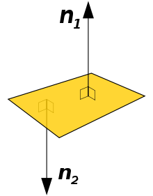
Normal vectors of a flat surface.
Remember that vectors have no location, just direction. Therefore a single vector can represent the direction of the front face for all points on the surface of the triangle.
Please note the following about the direction/orientation of a triangle:
- The vector that is pointing away from the front side of the triangle and is at a right-angle to every point in the surface of the triangle is called the normal vector. It is often just called the normal.
- The normal vector can be calculated “on the fly,” as needed, (assuming a triangle’s winding order is correct), or it can be calculated once and stored with the triangle’s definition. This is the classic computer science problem of resource allocation. If the normal is calculated as needed, the CPU (or GPU) has to do more work every time the triangle is rendered. If the normal is stored with the triangle definition, then more memory is required to store each triangle.
- If a normal vector is pre-calculated and stored with a model, it is always normalized to unit length because this minimizes the mathematical calculations needed during repeated rendering.
- There is never a need to calculate or store both the front and back facing normal vectors since they point in exactly opposite directions. If the front facing normal vector is <3,-2,5>, then the back facing normal vector is <-3,2,-5>.
Defining 3D Objects
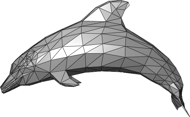
An example triangular mesh (Source1)
The form of any 3-dimensional object can be approximated with a set of triangles called a triangle mesh. The “dolphin” image shows an example.
The accuracy of an object’s form is dependent on the number of triangles used to model it. There is always the following trade-offs:
- Use a minimal number of triangles, which means the object’s form is a rough approximation, but rendering is very fast using very little memory.
- Use many triangles, which means the object’s form is accurate, but rendering takes more time and the RAM and GPU memory requirements are much larger.
The images below show how an object’s form can be more closely approximated as you increase the number of triangles. (3)
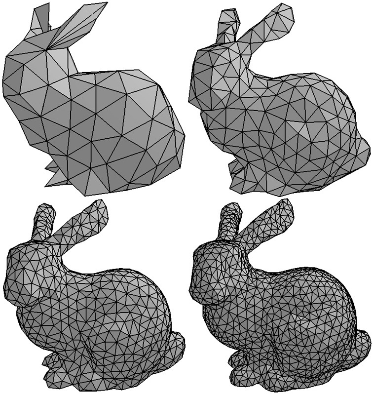
Refining a model’s form by adding triangles.
A triangle mesh that defines a solid object will have only some of its triangles visible from a particular point of view. If the density of the triangles is uniform over the entire surface of the object, then, on average, only half of a model’s triangles will be visible at any given time. There is a simple test to determine if a triangle is visible. Calculate the angle between a vector that is pointing in the direction of the camera’s view, and a triangle’s normal vector. If the angle is greater than 90 degrees, then the triangle’s front face is oriented away from the camera and will not be visible – it will be hidden by other triangles in the model that are facing towards the camera. The angle between two vectors can be calculated by taking their dot-product. This simple test is called face culling and can potentially speed up rendering by a factor of two.
Please note that face culling can only be done on models of solid objects. If a model does not completely enclose the interior of a model, the triangles that are sometimes visible from their back face will not be rendered properly.
WebGL Triangle Rendering Modes
In WebGL you always define a set of triangles using an array of vertices. There are three different ways the vertices can be used to form triangles, as shown in the diagram below. The options are:
- TRIANGLES - Three vertices for each triangle. Each vertex is used for one triangle. Vertices that are used for more than one triangle must be repeated in the vertices array. Defining n triangles requires 3n vertices.
- TRIANGLE_STRIP - After the initial three vertices, each additional vertex defines one more triangle. Defining n triangles requires (n + 2) vertices.
- TRIANGLE_FAN - All triangles share the first vertex. After the first two vertices, each new vertex creates one more triangle. Defining n triangles requires (n + 2) vertices.
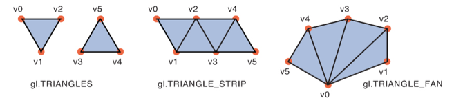
WebGL triangle drawing modes. (4)
Dividing a triangle mesh into the most efficient groups of TRIANGLES, TRIANGLE_STRIP, and TRIANGLE_FAN sets is a very difficult problem. You can save considerable amounts of memory by using TRIANGLE_STRIP, and TRIANGLE_FAN modes, but they are actually rarely used. Let’s consider a very simple example. A cube is defined by 8 vertices and 12 triangles (6 sides with 2 triangles per side). Here are many ways the cube could be rendered, such as
- Use TRIANGLES mode for all triangles. This requires an array of 36 vertices (12 triangles * 3 vertices/triangle).
- Use 2 arrays and TRIANGLE_FAN mode. One fan would start with the lower-left corner; the other fan would start with the upper-right corner. Each fan would draw 6 triangles. This requires two arrays of 8 vertices each, for a total of 16 vertices.
- Use TRIANGLE_STRIP mode to draw the front, right, back and left sides. Then use 2 TRIANGLE_FAN modes: one for the top 2 faces and one for the bottom 2 faces. This requires an array of 10 vertices for the TRIANGLE_STRIP and 2 arrays for the top and bottom, each holding 4 vertices. This is a total of 18 vertices.
- Etc. (Many other combinations are possible.)
The optimization of triangle groups to minimize memory requirements is beyond the scope of these tutorials. We will restrict ourselves to using TRIANGLES mode for all our renderings – at the cost of using more RAM and GPU memory.
Glossary
- virtual
- Something that does not physically exist but is created by software to appear real. A virtual world is a simulated, artificial, imitation of the real world – or a make-believe world that exists only in your mind.
- object
- A single entity in a virtual world that has a location, takes up some volume of space, and can be moved, scaled, and rotated.
- model
- A mathematical description of an object.
- scene
- A collection of objects that make up a virtual world. A scene contains objects that we want to visualize.
- rendering
- The process of creating an image from a collection of virtual objects. The image is a representation of what is visible from a virtual camera. The objects are only visible if there is virtual lighting in the scene.