8.1 - Introduction to Projections
When you render a 3-dimensional computer graphics scene, you create a 2-dimensional picture of the 3D scene. The picture is a projection of the models in the scene onto a 2-dimensional “screen”. Therefore it is logical to call this operation in the graphics pipeline a projection.
There are two standard projections used in computer graphics. An orthographic projection maintains parallel lines but provides no sense of depth. A perspective projection provides for a sense of depth, but parallel lines are skewed toward vanishing points. Orthographic projections are used in the engineering fields when an accurate representation of a model is desired. Perspective projections are used when a “real life” view of a scene is desired. Perspective projections simulate how the human eye sees the real world. Please study the following two examples and compare their outputs. You can rotate the view in both windows with a mouse click and drag.
An example of an orthographic projection. Notice that:
- Parallel lines stay parallel.
- There is no perception of depth. (The duplicated object in the background looks as big as the center object.)
An example of a perspective projection. Notice that:
- Parallel lines of the model are not parallel in the rendering.
- You can perceive depth. (The off-center object changes size as its distance from the camera changes.)
Each step in the graphics pipeline is performing a specific task but also preparing data for follow-on steps. This is especially true for the projection transform.
- The major task of a projection transformation is to project a 3D scene onto a 2D screen.
- A projection transformation also prepares for these follow-on tasks:
- Clipping - the removal of elements that are not in the camera’s line of sight.
- Viewport mapping - convert a camera’s viewing window into the pixels of an image.
- Hidden surface removal - determining which objects are in front of other objects.
Before a projection operation a (x,y,z) vertex represents a location in 3-dimensional space. After a projection the meaning of the values have changed:
- The (x,y) values of a vertex represent its location on a 2-dimensional screen.
- The z value represents the distance of the vertex from the virtual camera and is used for hidden surface removal.
- All 3 values, x, y, and z, are used for clipping, which removes points, lines, or triangles that are not visible to the scene’s virtual camera.
Before we jump into the details of projections, we need to discuss the standard clipping volume that all scenes are mapped into before they are rendered.
The Clipping Volume
When you point a real camera at something to take a picture, only a part of the real-world is visible in the camera’s field-of-view. The same is true of the human eye; you only see what is in front of you. We want the same behavior for our virtual scenes. The process of determining what is visible and what is not visible is called clipping. Clipping is done automatically by WegGL. To make clipping as efficient as possible, clipping is done using a cube centered at the origin.
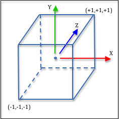
The clipping volume is defined in Normalized Device Coordinates (NDC) which is a 2 unit wide cube, with the X axis going from -1 to +1, the Y axis going from -1 to +1, and the Z axis going from -1 to +1, as shown in the image to the right.
Did you notice that the clipping volume is defined in a left-handed coordinate system? The Z-axis is pointing into the page. Wow! Previous lessons have stated that WebGL always uses a right-handed coordinate system and now it doesn’t. What is going on?
The short story is this: the hardware GPU that produces the graphics is designed for speed and efficiency, while the WebGL API is designed for programmers. Most people are right handed, so for most people the right-hand rule feels natural and comfortable, while the internal workings of the graphics hardware can typically be ignored. The projection matrix is the last operation under programmer control that manipulates the geometric data of a scene. So the projection transformation can convert to a left-handed coordinate system and not affect anything the programmer has done with the geometric data in a right-handed coordinate system.
You can visually see the left-handed coordinate system of the GPU in the following demo program. Observe what happens when you include an projection matrix and when you don’t.
Render 3 triangles with or without a projection matrix.
- The red triangle is at z = -0.25
- The green triangle is at z = 0.0
- The blue triangle is at z = +0.25
Use a projection matrix for rendering
Open this webgl program in a new tab or window
Given that the clipping volume uses a left-handed coordinate system, there are two very important implications to the graphics programmer:
- You must always include a projection matrix in your vertex transform, even if you don’t think you need one. All of the transformations we have defined previously assumed a right-handed coordinate system. If you don’t include a projection matrix, all of the other transformation matrices will not work correctly.
- If you create your own projection matrix, it should negate the z values of all vertices.
Clipping
Consider how clipping points might be done using programming logic. To determine if a point defined as (x,y,z) is inside the clipping volume, you could write code like this:
if (x >= -1 and x <= 1 and
    y >= -1 and y <= 1 and
    z >= -1 and z <= 1)
  point_is_visible = true;
else
  point_is_visible = false;
However, since the clipping volume is uniform and symmetrical about the origin, we can simplify this code using an absolute value function:
if (abs(x) <= 1 and abs(y) <= 1 and abs(z) <= 1)
     point_is_visible = true;
else
     point_is_visible = false;
Furthermore, you could set the boolean value with just a simple assignment like this:
point_is_visible = (abs(x) <= 1 and abs(y) <= 1 and abs(z) <= 1)
Actually clipping is done in homogeneous coordinates (which you will learn more about in a couple of lessons). For a (x,y,z,w) vertex, the clipping test would be
point_is_visible = (abs(x) <= w and abs(y) <= w and abs(z) <= w)
But the details don’t matter to most programmers. What does matter is that the symmetrical design of the clipping volume facilitates fast clipping. It is helpful to remember that WebGL is really a hardware specification with a software API (application programmer interface). WebGL’s design is optimized for hardware implementation.
When Does a Projection Need To Happen?
A projection transformation must happen after a scene has been moved in front of a virtual camera, but before clipping occurs. A projection operation can be performed using a 4-by-4 matrix multiplication, so it is typically combined with the model transform and the camera (or view) transform that have been conceptually performed in previous stages of the pipeline. In reality, the model, view, and projection transformations are typically performed with a single matrix multiplication. In your JavaScript code you will typically create a single transformation matrix and pass it to your vertex shader.
*ViewMatrix
*ModelMatrix
Eq1
The following lessons describe how to build a 4-by-4 projection matrix.
Glossary
- projection
- Transform the vertices of a 3D model into 2D points on a 2D viewing window.
- viewing window
- A rectangular 2D region on which a 3D world is projected.
- orthogonal projection
- Project all vertices of a 3D model along straight lines parallel to the Z axis.
- perspective projection
- Project all vertices of a 3D model along vectors to the camera’s location. Where the vector hits the 2D viewing window becomes it’s rendered location.
- clipping
- The process of determining what is visible and not visible in a virtual camera’s field of view.
- Normalized Device Coordinates (NDC)
- The 3D coordinate system that all scenes are converted into before clipping is performed.