8.2 - Orthographic Projections
Orthographic projections are used in the engineering fields to create accurate renderings of models. They maintains parallel lines but provide no sense of depth. All vertices are projected straight onto a viewing window. The distance from the virtual camera to an object has no affect on the size of the rendered object. In real life objects that are further from the camera appear smaller.
This lesson will describe how to create an orthographic projection and the mathematics behind its 4-by-4 transformation matrix.
The createOrthographic() function
The function createOrthographic() in the Learn_webgl_matrix.js module creates an orthographic projection transformation matrix. The function requires 6 parameters as shown in its function prototype below.
/** -----------------------------------------------------------------
 * Create an orthographic projection matrix.
 * @param left   Number Farthest left on the x-axis
 * @param right  Number Farthest right on the x-axis
 * @param bottom Number Farthest down on the y-axis
 * @param top    Number Farthest up on the y-axis
 * @param near   Number Distance to the near clipping plane along the -Z axis
 * @param far    Number Distance to the far clipping plane along the -Z axis
 * @return Float32Array The orthographic transformation matrix
 */
function createOrthographic(left, right, bottom, top, near, far)
The six parameters form a rectangular cuboid that defines the visible area of a rendering. Experiment with the example below which allows you to change the parameters to a createOrthographic function call and see the resulting rendering in the second canvas window to the right. You can click and drag in the left canvas to modify your view of the virtual world.
An orthographic projection demo.
Manipulate the parameters of the createOrthographic(left,right,bottom,top,near,far) function:
| X axis: -5.0 to 5.0 | Y axis: -5.0 to 5.0 | Z axis: -5.0 to 5.0 |
| left : -5.0 5.0 | | bottom: -5.0 5.0 | | near : -5.0 5.0 |
| right: -5.0 5.0 | | top : -5.0 5.0 | | far : -5.0 5.0 |
Open this webgl program in a new tab or window
As you experiment with the orthographic parameters, please make sure you observe the following characteristics of an orthographic projection.
- Primitive elements (points, lines, or triangles) outside the viewing volume are clipped from view. (Individual elements can be partially visible.)
- There are two identical models, but each is located a different distance from the camera. Notice that both models are rendered the same size.
- Notice that parallel lines in the models are parallel in the rendering.
- If the aspect ratio of the projection’s width and height is different than the aspect ratio of the canvas’ width and height, the rendering is distorted. It is your job as the programmer to make sure the aspect ratios are consistent.
- Values for left, right, bottom and top are intuitive. Values for near and far are not intuitive. Bottom line, think of the range of values along the z-axis you want included in the rendering. Near will be the largest z value, while far will be the smallest value. Then negate both values. For example, if you want to see everything between z = 10 and z = 2, then make near = -10 and far = -2. If you want to see everything between z = -3 and z = -12, then make near = 3 and far = 12. Very weird, though there is a pattern to the parameters. For example, if you want to see everything within 10 units of the origin, your parameters to createOrthographic would be (-10, 10, -10, 10, -10, 10). You can also think of the near and far values as distances down the -Z axis, with negative distances allowed.
- If the value of left is greater than the value of right, the world is mirrored about the Y axis. If the value of bottom is greater than the value of top, the world is mirror about the X axis. If you get the near and far values confused, clipping in depth will be backwards.
- The viewing window is the front side of the viewing volume. It is defined in the lower-left corner by the point (left, bottom, near) and in the upper-right corner by the point (right, top, near).
The Orthographic Projection Matrix
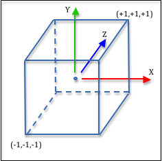
As we discussed in the previous lesson, a projection matrix must get the vertices in a scene into the clipping volume, which is a 2 unit wide cube shown in the image to the right. This is easily done with three transformations:
- Translate the volume defined by the createOrthographic parameters so that it is centered at the origin, then
- Scale the volume to be a 2 unit wide cube using an appropriate scale factor for each axis, and then
- Flip the z axis to match the clipping space’s coordinate system.
Let’s discuss the details of each step.
Center the Viewing Volume at the Origin
Let’s use a parametric equation to calculate the mid-point between two values. The mid-point is calculated when t is equal to 0.5. Therefore, the mid-point between left and right can be calculated like this:
mid_x = (1-0.5)*left + (0.5)*right; // t = 0.5
This reduces to the simple addition of left and right divided by 2.
mid_x = (left + right) / 2; // t = 0.5
We can calculate the center of the viewing volume using three such equations. We negate the near and far values to make them right-handed coordinate system values.
mid_x = (left + right) / 2;
mid_y = (bottom + up) / 2;
mid_z = (-near + -far) / 2;
Therefore, we can translate the viewing volume to make it centered about the global origin using this transformation matrix:
0
0
0
0
1
0
0
0
0
1
0
-mid_x
-mid_y
-mid_z
1
Eq1
Scale the Viewing Volume
Scaling requires a simple ratio. If the current width of the viewing volume is 10 units wide, scaling the values to 2 units wide requires a scale factor of 2/10, or 1/5. Our scale factors must be:
scale_x = 2.0 / (right - left);
scale_y = 2.0 / (up - bottom);
scale_z = 2.0 / (far - near);
Our scaling transform looks like this:
0
0
0
0
scale_y
0
0
0
0
scale_z
0
0
0
0
1
Eq2
Switch Coordinate Systems
The only difference between a right-handed and left-handed coordinate system is the direction of the z-axis. Vertices can be switched between the two systems by multiplication of the z component by -1. Here is our transformation for the coordinate system swap:
0
0
0
0
1
0
0
0
0
-1
0
0
0
0
1
Eq3
The Orthographic Projection Transform
Conceptually an orthographic transformation is composed of these three sequential transformations applied from right to left:
0
0
0
0
1
0
0
0
0
-1
0
0
0
0
1
*scale_x
0
0
0
0
scale_y
0
0
0
0
scale_z
0
0
0
0
1
*1
0
0
0
0
1
0
0
0
0
1
0
-mid_x
-mid_y
-mid_z
1
*x
y
z
1
=x'
y'
z'
w'
Eq4
Click on the multiplication sign in the above equation to see the results. If you simplify the terms, you get this transformation:
0
0
0
0
2/(top-bottom)
0
0
0
0
-2/(far-near)
0
-(right+left)/(right-left)
-(top+bottom)/(top-bottom)
-(far+near)/(far-near)
1
Eq5
Summary
When you break down an orthographic projection into its basic components it is very understandable how the math is accomplishing the desired manipulations. If you want to understand complex transformations, break them down into their elementary steps.
An orthographic projection does not modify the relative relationships between the (x,y) values of vertices and therefore an object’s size does not change as it moves closer or farther from the camera. An orthographic projection does prepares vertices for clipping.