8.3 - Perspective Projections
Perspective projections render a virtual scene to make it appear like a view from a real-world camera. Objects further from the camera appear to be smaller and all lines appear to project toward vanishing points which skew parallel lines. Perspective projections are almost always used in gaming, movie special effects, and visualizations of virtual worlds.
This lesson will describe how to create a perspective projection and the mathematics behind its 4-by-4 transformation matrix.
The Viewing Volume of a Perspective Projection
(Source 1)
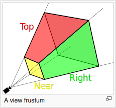
A perspective projection defines a 3D area that projects out from the location of the camera along four boundary rays. The rays form a viewing frustum as shown in the image to the right. The frustum includes a front and back clipping plane that is parallel to the X-Y plane. Any models inside this viewing frustum will be rendered. Any models outside this viewing frustum will be clipped away.
There are two standard ways to define a viewing frustum.
- The createPerspective() function simulates the lens of a camera. The camera is always at the global origin looking down the -Z axis.
- The createFrustum() function defines a 2D viewing window that is parallel to the X-Y plane. The camera can be located anywhere in the X-Y plane, but is always looking down a ray that is parallel to the -Z axis. A common use of this function is to render two different views of a scene, one for a user’s left eye and another for a user’s right eye. If the two renderings are offset correctly, and displayed to a user’s individual eyes, the user can see a 3D scene! This is how virtual reality (VR) is created.
Please study these two methods for creating perspective projections.
The createPerspective() function
The function createPerspective() in the Learn_webgl_matrix.js module creates a perspective projection transformation matrix. The function requires 4 parameters as shown in its function prototype below.
/** -----------------------------------------------------------------
 * Create a perspective projection matrix using a field-of-view and an aspect ratio.
 * @param fovy   Number The angle between the upper and lower sides of the viewing frustum.
 * @param aspect Number The aspect ratio of the viewing window. (width/height).
 * @param near   Number Distance to the near clipping plane along the -Z axis.
 * @param far    Number Distance to the far clipping plane along the -Z axis.
 * @return Float32Array The perspective transformation matrix.
 */
function createPerspective(fovy, aspect, near, far)
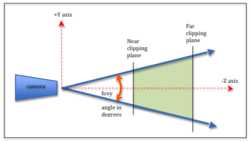
The four parameters define a frustum. The fovy parameter stands for the “field of view y-axis” and is the vertical angle of the camera’s lens. Common values for fovy range from 30 to 60 degrees. The aspect ratio parameter is the width divided by the height of the canvas window. The near and far distances are any positive numbers you wish to select, with the restriction that near is always less than far. The distance between near and far should be kept as small as possible to reduce precision issues since the frustum is being mapped into a clipping volume that is 2 units deep. Typical values for near and far might be 0.1 to 100.0. In general, make near as far away from the camera as possible and make far as close to the camera as possible.
Experiment with the parameters using the following demo.
A perspective projection demo.
Manipulate the parameters of the createPerspective(fovy,aspect,near,far) function:
| fovy : 5.0 179 | Field-of-view (y axis) = 45 degrees |
| aspect : 0.1 5.0 |
aspect = 1.00 (width/height) Change canvas size to match aspect ratio. |
| near : 0.1 10.0 | near = 1.0 |
| far : 2.0 20.0 | far = 10.0 |
Open this webgl program in a new tab or window
As you experiment with the perspective parameters, please make sure you observe the following characteristics of a perspective projection.
- As the angle for the camera’s lens (i.e., fovy) gets smaller, the objects in the scene get bigger. This is consistent with how light travels through the optics of a camera.
- If the aspect ratio changes but the canvas remains unchanged, the rendering will be distorted. It is your job as a programmer to make sure the aspect ratio of the perspective matches the aspect ratio of the canvas.
- The value of near has no impact on the rendered view. It does affect what is clipped from the scene. The same is true for the value of far.
- The near and far parameters are always positive and near should always be less than far. The near and far parameters are both distances – not Z axis values.
The createFrustum() function
The function createFrustum() in the Learn_webgl_matrix.js module creates a perspective projection transformation matrix. The function requires 6 parameters as shown in its function prototype below.
/** -----------------------------------------------------------------
 * Set a perspective projection matrix based on limits of a frustum.
 * @param left   Number Farthest left on the x-axis
 * @param right  Number Farthest right on the x-axis
 * @param bottom Number Farthest down on the y-axis
 * @param top    Number Farthest up on the y-axis
 * @param near   Number Distance to the near clipping plane along the -Z axis
 * @param far    Number Distance to the far clipping plane along the -Z axis
 * @return Float32Array A perspective transformation matrix
 */
function createFrustum (left, right, bottom, top, near, far)
The 3D points (left, bottom, near) and (right, top, near) define the lower-left and upper-right corners of the viewing window. If you calculate the center of the viewing window and cast this point back to the X-Y plane, this point is the apex of the frustum. Casting rays from the apex through the four points of the viewing window forms the frustum. (The location of the apex is displayed in the demo below as a small black dot.)
Experiment with the parameters using the following demo.
A perspective projection demo.
Manipulate the parameters of the createFrustum(left,right,bottom,top,near,far) function:
| X axis: -5.0 to 5.0 | Y axis: -5.0 to 5.0 | Z axis: 1.0 to 10.0 |
| left : -5.0 5.0 |
| bottom : | -5.0 5.0 |
| near : | 0.1 10.0 |
| right: -5.0 5.0 |
| top: | -5.0 5.0 |
| far: | 2.0 20.0 |
Open this webgl program in a new tab or window
As you experiment with the frustum parameters, please make sure you observe the following characteristics of the perspective projection it creates.
- createFrustum allows you to create a frustum that is “off center” from the -Z axis, but its field of view is always parallel to the -Z axis.
- It is your job as the programmer to make sure your canvas dimensions have an aspect ratio (width/height) that is consistent with the aspect ratio of your viewing window (right-left)/(top-bottom). If the aspect ratios are different, the rendering will be skewed.
- Changing the value of near has a profound affect on the frustum because this is the distance from the camera to the viewing window and the entire frustum is defined by the corners of the viewing window. Changing the near value is fundamentally changing your camera lens’ field-of-view (which was controlled by the fovy parameter in the createPerspective function described previously).
- Changing the value of far only affects clipping.
- Changing the values of left and right shifts the location of the camera away from the origin.
- Changing the values of top and bottom shifts the location of the camera away from the origin.
The Perspective Projection Matrix
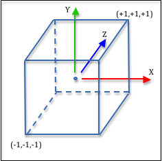
A projection matrix must get the vertices in a scene into the clipping volume, which is a 2 unit wide cube shown in the image to the right. Doing this for a perspective projection is more challenging than an orthographic projection because much more manipulation of the vertices is needed. The math is easy, but it requires some special tricks to get the math into a 4x4 transformation matrix. We need to perform the following steps to create a perspective projection transformation matrix:
- Translate the apex of the frustum to the origin.
- Perform the perspective calculation.
- Scale the 2D (x’,y’) values in the viewing window to a 2-by-2 unit square: (-1,-1) to (+1,+1).
- Scale the depth values (z) into a normalized range (-1,+1).
- Flip the orientation of the z axis to match the clipping volume’s orientation.
Let’s discuss these tasks separately.
Move the Frustum Apex to the Origin
A perspective frustum can be offset from the global origin along the X or Y axes. We need to place the apex of the frustum at the global origin for the perspective calculations to work. The apex is located in the center of the viewing window in the XY plane. Therefore we calculate the center point of the viewing window and translate it to the origin. Notice that the z value is unchanged.
mid_x = (left + right) * 0.5;
mid_y = (bottom + top)  * 0.5;
0
0
0
0
1
0
0
0
0
1
0
-mid_x
-mid_y
0
1
*x
y
z
1
=x'
y'
z'
w'
Eq1
or
0
0
0
0
1
0
0
0
0
1
0
-(left+right)/2
-(bottom+top)/2
0
1
*x
y
z
1
=x'
y'
z'
w'
Eq2
The Perspective Calculation
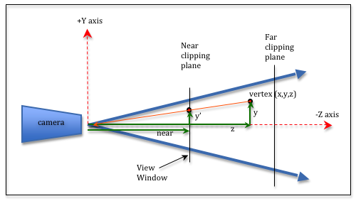
We need to project every vertex in our scene to its correct location in the 2D viewing window. The 2D viewing window is the near plane of the frustum. Study the diagram to the right. Notice that the vertex (x,y,z) is projected to the viewing window by projecting a ray to the camera (shown as an orange ray). The rendering location for the vertex is (x',y',near). From the diagram you can see that the y and y' values are related by proportional right-triangles. These two triangles must have the same ratio of side lengths. Therefore, y'/near must be equal to y/z. Solving for y' gives (y/z)*near, or y' = (y*near)/z. Note that near is a constant for a particular scene, while y and z are different for each vertex in a scene. Using the same logic, x' = (x*near)/z.
To summarize, we can calculate the location of a 3D vertex in a 2D viewing window with a multiplication and a division like this:
x' = (x*near)/z
y' = (y*near)/z
To be precise, since all of the z values for vertices in front of the camera are negative, and the value of z is being treated as a distance, we need to negate the value of z.
x' = (x*near)/(-z)
y' = (y*near)/(-z)
But we have a problem. A 4-by-4 transformation matrix is a linear combination of terms. That is, we can do calculations like a*x + b*y + c*z + d, but not calculations like a*x/z + ..., where the x and z component values of a vertex are used in a single term. But we have a solution using homogeneous coordinates. Remember that a vertex defined as (x,y,z,w) defines a location in 3D space at the point (x/w, y/w, z/w). Normally the w component is equal to 1 and the (x,y,z) values are exactly that, (x,y,z). But to implement perspective division we can set the w value to our divisor, (-z). This breaks the above calculations into two parts. A matrix transform will perform the multiply. A post-processing step, after the matrix multiplication, will perform the homogeneous division.
To perform the multiplication in the perspective calculation, we can use this matrix transformation:
0
0
0
0
near
0
0
0
0
1
0
0
0
0
1
*x
y
z
w
=x'
y'
z'
w'
Eq3
To get the divisor, (-z), into the w value, we can use this transform:
0
0
0
0
1
0
0
0
0
1
-1
0
0
0
0
*x
y
z
w
=x'
y'
z'
w'
Eq4
It is easy to show that these can be combined into this single transformation matrix which performs our perspective calculation and setup for division:
0
0
0
0
near
0
0
0
0
1
-1
0
0
0
0
*x
y
z
w
=x'
y'
z'
w'
Eq5
The graphics pipeline is designed to expect the perspective divisor in the w component. The pipeline always calculates (x/w, y/w, z/w) before passing a vertex’s values onto the remaining stages.
Scale the View Window to (-1,1) to (+1,+1)
Subsequent stages in the graphics pipeline require that the 2D viewing window be normalized to values between (-1,-1) to (+1,+1). We need to scale the x and y values to a 2-by-2 square. This is easily done with a scale factor based on a simple ratio: 2/currentSize. The equations and the resulting matrix transformation are:
scale_x = 2.0 / (right - left);
scale_y = 2.0 / (top - bottom);
0
0
0
0
2/(top-bottom)
0
0
0
0
1
0
0
0
0
1
*x
y
z
w
=x'
y'
z'
w'
Eq6
Mapping Depth (z values) to (-1,+1)
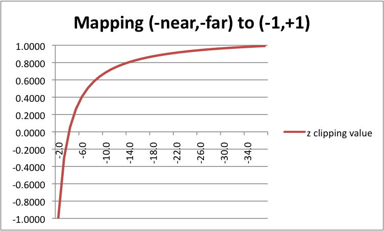
We have calculated the correct location for a vertex in the 2D viewing window, but we have not changed the z component. We can’t discard the z value; it tells us the distance between a vertex and the camera, which allows us to determine which objects are in front of other objects. We could easily do a linear mapping between the range (-near,-far) to (-1,+1). However, floating point numbers suffer from round-off errors when they are manipulated. In graphics applications, sometimes the difference between 0.1234568 and 0.1234567 can have a visual impact on a rendering. We would like to use more precision for values close to the camera and less precision for vertices farther from the camera. This means we want a non-linear mapping between (-near,-far) and (-1,+1).
The non-linear equation used for the mapping is c1/-z + c2, where c1 and c2 are constants that are calculated based on the range (-near,-far). When z = -near, the equation must calculate -1. When z = -far, the equation must calculate +1. This gives us two equations to solve for c1 and c2.
-1 = c1/-(-near) + c2
+1 = c1/-(-far)  + c2
Using a little algebra, we get
c1 = 2*far*near / (near - far)
c2 = (far + near) / (far - near)
Let’s consider an example before we proceed. Suppose near = 2.0 and far = 40. This means that vertices with a z component value between -2 and -40 will be included in the clipping volume. To the right is a list of z values and their corresponding mapping to the range (-1,+1). There is also a plot of these values below. Notice that the z values between -2 and -3.8 use up half of the clipping volume values (-1.0, 0.0)! That is definitely non-linear!
But hold on! We have the same problem we had with the perspective calculation! You can’t put put a term like c1/-z + c2 into a transformation matrix. So we use the same trick we used for the perspective divide – we postpone the division until the homogeneous divide step after the transformation. We can write the mapping equation like this: c1/-z + c2*(-z)/(-z) which is equivalent to (c1 + c2*(-z))/(-z). Let’s rearrange the terms to match our transformation matrix format: (-c2*z + c1)/(-z). We can put the top portion of this equation in our matrix transformation and let the homogeneous divide take care of the division later.
0
0
0
0
1
0
0
0
0
-c2
-1
0
0
c1
0
*x
y
z
1
=x'
y'
z'
w'
Eq7
Notice that we need to do this transform while w is still 1.0.
Switching Coordinate Systems
The last step is to swap the direction of the z axis to match the clipping volume orientation. However, we don’t need to do this because when we mapped the z values to a non-linear range, the new range was -1 to +1 which effectively switched the direction of the z axis.
Building the Prospective Projection Transform
Let’s put all of the above concepts together into a single perspective transformation matrix. We list the steps below so you can match each step to its individual transform. However, we need modify things slightly to account for the combination of these transformation matrices. Step 2 and 3 both need to make w be equal to (-z). We don’t want to do this twice, so we delete the -1 term in the perspective transform. In addition, we don’t need to swap the orientation of the coordinate axes because when we mapped the z values to (-1,+1) the values got flipped by the mapping. Finally, we reorder the scaling of the depth values to make sure it is performed when the w component is 1.0.
- Translate the apex of the frustum to the origin. (Yellow matrix)
- Scale the depth values (z) into a normalized range (-1,+1) (and setup for division by (-z)). (Purple matrix)
- Perform the perspective calculation. (Gray matrix)
- Scale the 2D (x’,y’) values in the viewing window to a 2-by-2 unit square; (-1,-1) to (+1,+1). (Cyan matrix)
0
0
0
0
2/(top-bottom)
0
0
0
0
1
0
0
0
0
1
*near
0
0
0
0
near
0
0
0
0
1
0
0
0
0
1
*1
0
0
0
0
1
0
0
0
0
-c2
-1
0
0
c1
0
*1
0
0
0
0
1
0
0
0
0
1
0
-(left+right)/2
-(bottom+top)/2
0
1
*x
y
z
1
=x'
y'
z'
w'
Eq8
If you click on the multiplication signs in the above equation from right to left you can see the progression of changes to a (x,y,z,w) vertex at each step of the transformation.
If you simplify the matrix terms and substitute the equations for c1 and c2 you get this transformation:
0
0
0
0
2*near/(top-bottom)
0
0
0
0
-(far+near)/(far-near)
-1
-near*(right+left)/(right-left)
-near*(top+bottom)/(top-bottom)
2*far*near/(near-far)
0
Eq9
You will probably never implement code to create a perspective projection. It has been implemented for you in the learn_wegbl_matrix.js code file. So what value was there in going through all of the above discussion? Many operations in computer graphics are performed by transformation matrices. If you can master the art of creating combinations of transformations, you can create amazing computer graphics programs. The previous discussion has hopefully helped you think in terms of chaining matrix transformations to achieve a particular goal.
Comparing createPerspective() vs. createFrustum()
Let’s compare the functions createPerspective() and createFrustum().
How are they similar?
- Both create a perspective transformation matrix.
How are they different?
- They require different parameters to define the frustum viewing volume.
- The createPerspective() function only allows the viewing frustum to be centered at the global origin.
- The createFrustum function allows the viewing frustum to be offset from the global origin along the X or Y axis.
To demonstrate the equivalence of the functions, the following two examples show how you could use one function to implement the other one.
function createPerspectiveUsingFrustum (fovy, aspect, near, far) {

  var top, bottom, left, right;

  top = near * Math.tan(toRadians(fovy)/2);
  bottom = -top;
  right = top * aspect;
  left = -right;

  return createFrustum(left, right, bottom, top, near, far);
}

function createFrustumUsingPerspective (left, right, bottom, top, near, far) {
  var fovy, aspect;

  fovy = 2 * toDegrees(Math.atan2(top, near));
  if (-left === right && -bottom === top ) {
    aspect = right / top; // width / height

    return createPerspective(fovy, aspect, near, far);
  }
}
Summary
When you break down a perspective projection into its basic components it is very understandable how the math is accomplishing the desired manipulations. If you want to understand complex transformations, break them down into their elementary steps.
Fundamentally a perspective projection changes the x and y values of every vertex based on its distance to the camera. It also prepares the vertices for clipping.