8.4 - Viewports
After a projection transformation your models are ready for clipping, which discards any primitive elements (points, lines or triangles) that are not inside the camera’s field of view. After clipping its time to create an image!
This lesson describes how a scene’s geometric data is mapped to a 2D image.
The Viewport Transformation
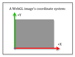
Your geometric data has (x,y,z) values which are inside a 2-by-2-by-2 clipping volume centered at the origin. Its time for the pipeline to start creating a 2D image. The image will be mapped into a HTML canvas element, so the image is created to be the same size (in pixels) as the canvas element . A WebGL image uses a coordinate system that has an origin in the lower-left corner, with the +X axis going to the right and the +Y axis going up, as shown in the image to the right. The vertex data from the clipping volume needs to be mapped into image locations. This is done with two simple transformations:
- Scale the (-1,-1) to (+1,+1) viewing window to the image’s width and height.
- Offset the lower-left corner at (-width/2,-height/2) to the image’s origin.
In matrix format, this transformation is
0
0
0
0
1
0
0
0
0
1
0
width/2
height/2
0
1
*width/2
0
0
0
0
height/2
0
0
0
0
1
0
0
0
0
1
*x
y
z
1
=xImage
yImage
zDepth
1
Eq2
Notice that we are only transforming the x and y coordinated of each vertex because we are creating a 2D image. The z component is carried along with the vertex, but its value remains unchanged.
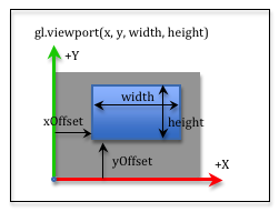
You don’t implement the viewport transformation. It is done internally by the graphics pipeline. But you can specify that you only want your rendering to fill part of a canvas. By default, the width and height of your canvas is the viewport’s width and height. If you would like to render a smaller image, you can specify an offset and a size for the smaller image using the gl.viewport(x_offset,y_offset,width,height) function. The x_offset and y_offset parameters specify the offset from the lower left corner and the width and height specify the size of rendered image. The transformation for this smaller image is:
0
0
0
0
1
0
0
0
0
1
0
x_offset
y_offset
0
1
*1
0
0
0
0
1
0
0
0
0
1
0
width/2
height/2
0
1
*width/2
0
0
0
0
height/2
0
0
0
0
1
0
0
0
0
1
*x
y
z
1
=xImage
yImage
zDepth
1
Eq2
The following demonstration program renders two separate images into a single canvas. The first image is displayed in the entire canvas, while the second image is displayed in the lower-right corner.
An example of a viewport rendering. The entire canvas is being rendered with a view of a virtual world, while a second rendering is being placed into a lower-right viewport.
Manipulate the parameters of the createPerspective(fovy,aspect,near,far) function:
| fovy : 5.0 179 | Field-of-view (y axis) = 45 degrees |
| aspect : 0.1 5.0 |
aspect = 1.00 (width/height) Change canvas size to match aspect ratio. |
| near : 0.1 10.0 | near = 1.0 |
| far : 2.0 20.0 | far = 10.0 |
To accomplish the two renderings in a single canvas you also have to use a gl.SCISSOR_TEST. The default behavior for all WebGL commands is to operate on the entire image it is creating. If you want to change only a portion of the image, you can enable the gl.SCISSOR_TEST and set the limits of the image that can be changed. If you study the code in the above example, the initialization code for the program enables the scissor test in line 266:
gl.enable(gl.SCISSOR_TEST);
When the entire canvas is rendered, the viewport and the scissor limits are set to the entire canvas in lines 131-132:
gl.viewport(0, 0, canvas_width, canvas_height);
gl.scissor(0, 0, canvas_width, canvas_height);
When the smaller image is rendered, the viewport and the scissor limits are set to the lower-right corner of the canvas in lines 195-196:
gl.viewport(x_offset, y_offset, width, height);
gl.scissor(x_offset, y_offset, width, height);
Mouse Events into World Locations
You sometime need to convert the location of a mouse cursor into a location in your 3D virtual scene. Since you are viewing a 3D world, a mouse location actually identifies an infinite number of points that lie on a ray from the camera through the mouse’s location into the 3D world. You can convert a mouse location into a viewing window location using simple proportions. Study the two diagrams below.
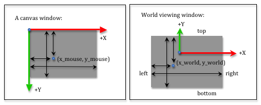
The screen coordinates used by a mouse have the +Y axis going down the screen, but this does not matter if you use the same distances for your proportions. In both diagrams we measure distances from the left side and the top side. We use the variables left, right, bottom and top that were used to define our projection matrices to describe the world viewing window. Let’s use canvas_width and canvas_height to describe the size of the canvas window. The relative distances in both windows must be the same. Therefore:
x_mouse / canvas_width  === (x_world - left) / (right - left)
y_mouse / canvas_height === (top - y_world)  / (top - bottom)
If you know a mouse location, (x_mouse, y_mouse), you can solve the above equations to calculate the equivalent location in the virtual world on the viewing window. That is:
x_world = [(x_mouse / canvas_width) * (right - left)] + left;
y_world = top - [(y_mouse / canvas_height) * (top - bottom)];
If you want to convert a location in the viewing window to a mouse location, you can solve to get these equations:
x_mouse = [(x_world - left) / (right - left)] * canvas_width;
y_mouse = [(top - y_world)  / (top - bottom)] * canvas_height;
Glossary
- viewport
- The portion of an HTML canvas you want to render into. The default viewport is the entire canvas.