8.5 - Summary of Projections and Viewports
This set of lessons on projections and viewports, along with the previous lessons on camera and model transformations has made extensive use of 4-by-4 transformation matrices. Mastering the use of 4-by-4 transformation matrices is fundamental to learning how to create 3D computer graphics.
This lesson puts everything we have been discussing in sections 6, 7 and 8 into perspective (no pun intended)!
A Graphics Pipeline Review
To understand computer graphics you have to understand the graphics pipeline. Let’s review the graphics pipeline again.
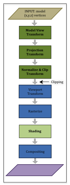
You have a set of models you want to render to compose a virtual scene. The models contain two basic types of data:
- Geometric data composed of vertices, (x,y,z), and normal vectors, <dx,dy,dz>, and
- Material properties data such as colors, texture coordinates, shininess coefficients, etc..
This data is passed through the graphics pipeline to create a 2D image of the scene. The first half of the pipeline deals with the geometry data, while the second half deals with the material properties data.
In the first three stages:
- The geometric data is transformed using a 4-by-4 transformation matrix to place the geometry of the model in its desired location, orientation, and size. This is referred to as the “model transform.”
- The geometric data is transformed using a 4-by-4 transformation matrix to place the scene in front of the camera. This is referred to as the “view transform” (or the “camera transform”).
- The geometric data is projected onto a 2D viewing window. This is referred to as the “projection transform.”
All of these transformations happen in a vertex shader program. You create the needed transformation matrices in a JavaScript program, and a vertex shader program, which is running on the GPU, performs the actual geometric data transformations. Most WebGL programs combine all of these transformations into a single 4-by-4 transformation matrix, where the ordering from right to left is critical because the model transformation must happen first, then the view transformation and finally the projection transformation. In matrix format, your JavaScript program creates:
*ViewMatrix
*ModelMatrix
Eq1
Your geometric data has been transformed into the clipping volume – a 2x2x2 cube centered at the origin. All geometry outside this cube is clipped away. Now the pipeline starts to create a 2D image by mapped the vertices into a 2D array of pixels that is the same size as its associated HTML canvas element. This is referred to as the “viewport transform.”
The geometry data is now positioned in the correct place to create a 2D image. But all of these transformations have only been done on the vertices of the points, lines and triangles that compose your models. All of the pixels that compose a primitive object have not been determined. That is the next step in the pipeline and it is called the “rasterization” (or rasterisation) stage.
Rasterize
To rasterize means to convert vector based descriptions of a geometric object into a set of pixels. For example, if we know the pixel locations of three vertices that define a triangle, to rasterize the triangle means we determine which pixels lie inside the boundaries formed by the triangle’s vertices and edges. The rasterization stage of the pipeline is done automatically.
For each pixel that is used to compose a primitive object, a “fragment” is created. A fragment knows its pixel location and other information that might be needed to assign the pixel a color. Each “fragment” that is created is passed through a fragment shader executing on the GPU. A fragment shader program performs calculations that assign an appropriate color to its pixel.
The remainder of these tutorials will discuss how a fragment shader calculates the color of a pixel.
Glossary
- rasterize
- Convert a vector based description of a geometric object into a set of pixels.
- fragment
- A group of values related to an individual pixel in an image.
- fragment shader
- A computer program, written in GLSL, that calculates a color for a pixel using information contained in a fragment.