9.2 - Light Models
We need a description of a light source that can be used to calculate the reflection of light. We call such a description a “lighting model”. Let’s start as simple as possible. Then future lessons will add more details to create more accurate lighting affects.
A Review of Light Properties
Please re-read lesson 3.8 - Light Modeling.
Did you really re-read lesson 3.8. If not, please read it now. It’s important!
Getting the Correct Data
To calculate light reflection, we need to have the position and orientation of three things:
- The object being rendered,
- The light source, and
- The camera.
Please note the following about these three things:
- A scene rendering has exactly one camera. The definition of the camera is not be stored in a GPU buffer object because it typically changes for each new rendering and because it is never actually rendered. Therefore the definition of the camera must be passed from the CPU’s RAM to the GPU’s shader programs.
- A scene rendering has one or more light sources, but the light sources are not typically rendered. You might render an object at the location of a light source, such as a light bulb, but that is a separate issue. The definition of a light source is not stored in a GPU buffer object; its definition must be passed from the CPU’s RAM to the GPU’s shader programs.
- A typical scene rendering contains multiple objects. Each individual object is stored in a GPU buffer object.
Therefore, for a typical rendering, the camera and light source data is passed to the GPU as uniform variables, while the object (model) data is already in the GPU’s memory as a buffer object. The less data we pass from the CPU’s RAM to the GPU, the faster the rendering.
A camera, light source, and object model each have a position and orientation based on their initial definition, but these are transformed to new locations and orientations for a particular scene. Consider the three fundamental transformations done on the vertices of a model shown in the diagram below, which gives us four possible positions and orientations for lighting calculations.
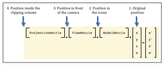
For lighting calculations, what are the advantages and/or disadvantages in using these possible positions?
- The original position: We can’t use this location. This does not represent where the object is for a particular scene.
- Position in the scene: This is the position after being transformed by the model transform. This is the location we want. It places the object’s location relative to the other objects in the scene. If we use this location, we need to pass a complete definition of the camera to the shader programs, which includes an eye location and three axis vectors, and a complete definition of the light source.
- Position in front of the camera: This is also a valid position because it has the same relative location as the position in the scene. And notice that the camera is located at the origin with its local coordinate system aligned to the global coordinate system. This has the advantage that we don’t have to send the camera’s location and orientation to the shader programs because we know exactly where the camera is. A complete definition of the light source must be passed to the shader programs.
- Position inside the clipping volume: This is not a valid position because the perspective transformation has decoupled the meaning of the x and y values from the z value of each vertex. The vertices no longer have their same relative relationship with other 3D positions in the scene. (Remember, the perspective transform did a non-linear mapping of the z values into the clipping volume.)
So we have a clear choice. We should perform lighting calculations using positions that have been transformed by the model and camera transformations, but not the projection transformation. This means we need to calculate two separate transformation matrices. This matrix:
*ViewMatrix
*ModelMatrix
*x
y
z
w
=x'
y'
z'
w'
Eq1
will transform the geometry in a scene for rendering, while the transformation matrix below will produce valid locations for lighting calculations.
*ModelMatrix
*x
y
z
w
=x'
y'
z'
w'
Eq1
Basic Scenario
Here are the basic steps to render a scene that uses lighting calculations to assign a color to a pixel. We have a light source definition that includes its position and orientation, and we know how to move it and orient it into a scene.
- In your JavaScript program:
- Use a model and camera transformation to get the light source into its desired position and orientation.
- Pass the light source’s position and orientation to the GPU’s shader programs
- Create an additional transformation matrix that includes a projection matrix.
- Pass two transformation matrices to the GPU’s shader programs; one for lighting calculations, another for rendering calculations.
- In your GPU shader program:
- Assume the camera is at the global origin looking down the -Z axis.
- Use the light source data and the model data to calculate light reflection.
- Assign a color to a pixel based on the light reflection.
Glossary
- projection
- Transform the vertices of a 3D model into 2D points on a 2D viewing window.
- viewing window
- A rectangular 2D region on which a 3D world is projected.
- orthogonal projection
- Project all vertices of a 3D model along straight lines parallel to the Z axis.
- perspective projection
- Project all vertices of a 3D model along vectors to the camera’s location. Where the vector hits the 2D viewing window becomes it’s rendered location.
- clipping
- The process of determining what is visible and not visible in a virtual camera’s field of view.
- Normalized Device Coordinates (NDC)
- The 3D coordinate system that all scenes are converted into before clipping is performed.