9.2 - Diffuse Lighting
This lesson discusses how to implement diffuse reflection of light.
A Simple Diffuse Lighting Model
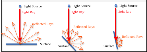
Diffuse light reflection.
Light that directly strikes an object and then reflects in all directions is called “diffuse” light. The amount of light reflection is determined by the angle between the light ray and the surface normal vector. In Physics, Lambert’s cosine law provides an equation for calculating diffuse color.
The Math for Diffuse Reflection
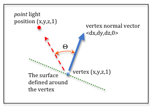
Diffuse reflection calculation.
To perform diffuse lighting calculations each vertex that defines a triangle must have an associated normal vector. The normal vector defines a direction that is projecting out from the front side of the triangle. The normal vector defines how light will reflect off of a surface defined at the vertex. The normal vector may be 90 degrees to the surface of the triangle, or it might be at some other angle to simulate a curved surface.
The diagram to the right labels the pieces needed to calculate diffuse reflection. We need to calculate the angle between the vertex’s normal vector and a vector pointing at the light source from the vertex. This angle is labeled “theta” in the diagram.
The dot product of two vectors is defined as the sum of the products of their associated terms. 3D vectors are normally stored as arrays, where (v[0], v[1], v[2]) is the <dx, dy, dz> values of the vector. Therefore, the dot product of vectors v0 and v1 is:
function dotProduct (v0, v1) {
  return v0[0] * v1[0]  +  v0[1] * v1[1]  +  v0[2] * v1[2];
};
It can be shown that the dot product of two vectors is equal to the cosine of the angle between the two vectors divided by the length of the two vectors. In code format, this means that:
dotProduct(v0, v1) === cos(angle_between_v0_and_v1) / (length(v1) * length(v2))
If both v0 and v1 are normal vectors that have a length of 1, the dot product gives the cosine of the angle without any division.
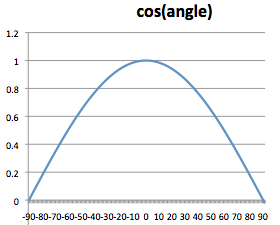
Examine the plot of a cosine curve to the right. Notice that when the angle is zero, the cosine of zero is 1.0. As the angle increases, the cosine of the angle curves to zero. When the angle is 90 degrees, the cosine of 90 is 0.0. This is lambert’s cosine law. The cosine values are treated as percentages of color. When the angle is zero, cos(0) is 1.0, and you get 100% color. When the angle is 90 degrees, cos(90) is zero and you get 0% color. When the angle becomes greater than 90 or less than -90 the cosine goes negative. This is an indication that the front side of the triangle is pointing away from the light source. You can’t have a negative percentage of light, so we clamp the cosine of the angle to values between 0.0 and 1.0.
A WebGL Demo Program for Diffuse Lighting
Experiment with the following WebGL program. Move the light source and examine how the colors on the model change.
Manipulate the position of a light source and a camera.
The left canvas shows the relative location of the light source, the camera, and an object.The right canvas shows the scene from the camera's vantage point with the light source used to calculate diffuse reflection.
| Manipulate the camera's location and center of view: | Manipulate the light's location: | |
| eye (0.0, 0.0, 5.0) | center (0.0, 0.0, 0.0) | light (3.0, 3.0, 3.0) |
| X: -5.0 +5.0 | X: -5.0 +5.0 | X: -5.0 +5.0 |
| Y: -5.0 +5.0 | Y: -5.0 +5.0 | Y: -5.0 +5.0 |
| Z: -5.0 +5.0 | Z: -5.0 +5.0 | Z: -5.0 +5.0 |
Open this webgl program in a new tab or window
As you experiment with the demonstration program, please make sure you observe the following characteristics of diffuse reflection.
- Moving the camera has no impact on diffuse reflection. The only elements involved in the calculations are the object’s vertices and the location of the point light source.
- If you move the light source close to a particular face, every pixel on the face potentially has a different color. The program is calculating the diffuse reflection in the fragment shader pixel by pixel.
- Notice that some faces that are “blocked” from the light still have a bright color. That is, the face should be getting no light because there is an object between it and the light source. However, our simple light model does not account for light being blocked by other objects in the scene. And most people never notice that fact!
- This lighting model does not account for the distance from the light to a surface. In the real world, the further an object is from a light source, the less light it receives. We will investigate this in later lessons.
Diffuse Reflection in Shader Programs
Please study the following shader programs. Then compare the programs to the comments below.
Vertex Shader
// Vertex Shader
precision mediump int;
precision mediump float;

// Scene transformations
uniform mat4 u_PVM_transform; // Projection, view, model transform
uniform mat4 u_VM_transform;  // View, model transform

// Light model
uniform vec3 u_Light_position;

// Original model data
attribute vec3 a_Vertex;
attribute vec3 a_Color;
attribute vec3 a_Vertex_normal;

// Data (to be interpolated) that is passed on to the fragment shader
varying vec3 v_Vertex;
varying vec4 v_Color;
varying vec3 v_Normal;

void main() {

  // Perform the model and view transformations on the vertex and pass this
  // location to the fragment shader.
  v_Vertex = vec3( u_VM_transform * vec4(a_Vertex, 1.0) );

  // Perform the model and view transformations on the vertex's normal vector
  // and pass this normal vector to the fragment shader.
  v_Normal = vec3( u_VM_transform * vec4(a_Vertex_normal, 0.0) );

  // Pass the vertex's color to the fragment shader.
  v_Color = vec4(a_Color, 1.0);

  // Transform the location of the vertex for the rest of the graphics pipeline
  gl_Position = u_PVM_transform * vec4(a_Vertex, 1.0);
}
- All calculations in the fragment shader will be done in “camera space,” so the vertex data is transformed by the model and camera transformations, but not the projection transformation.
- The shaders are based on three uniform variables:
- u_PVM_transforms: a single transformation matrix that contains the model, view, and projection transforms.
- u_VM_transforms: a single transformation matrix that contains the model and view transforms.
- u_Light_position: a single location (x,y,z) that contains the position of the point light source in “camera space.” (This location has already been placed in the scene and multiplied by the view transform.)
- The location, (x,y,z,1), normal vector, <dx,dy,dz,0>, and color, (red,green,blue,1), of this vertex that will be interpolated between the vertices of the primitive element. Therefore, we put this data into varying variables associated with this vertex.
- There are several conversions between 3-component and 4-component values. You need a 4-component value to perform matrix multiplication between a 4x4 matrix and a vertex or vector. Notice that a vertex always gets a 4th component of 1.0, while a vector always gets a 4th component value of 0. This is because vertices can be translated, while vectors have no position and can’t be translated.
Fragment Shader
// Fragment shader program
precision mediump int;
precision mediump float;

// Light model
uniform vec3 u_Light_position;

// Data coming from the vertex shader
varying vec3 v_Vertex;
varying vec4 v_Color;
varying vec3 v_Normal;

void main() {

  vec3 to_light;
  vec3 vertex_normal;
  float cos_angle;

  // Calculate a vector from the fragment location to the light source
  to_light = u_Light_position - v_Vertex;
  to_light = normalize( to_light );

  // The vertex's normal vector is being interpolated across the primitive
  // which can make it un-normalized. So normalize the vertex's normal vector.
  vertex_normal = normalize( v_Normal );

  // Calculate the cosine of the angle between the vertex's normal vector
  // and the vector going to the light.
  cos_angle = dot(vertex_normal, to_light);
  cos_angle = clamp(cos_angle, 0.0, 1.0);

  // Scale the color of this fragment based on its angle to the light.
  gl_FragColor = vec4(vec3(v_Color) * cos_angle, v_Color.a);
}
- This calculates the angle between a vector to the light and the vertex’s normal vector.
- Shaders implement vector and matrix math, so when you subtract two vec3 variables it is creating a vec3 result.
- The value of the vertex normal vector is an interpolation of the normals vectors at the triangle’s vertices. It is easy to show that this interpolated vector may not have a unit length. Therefore the v_Normal vector must be normalized for each fragment.
- The percentage of color must be between 0% and 100%. Since the cosine function can calculate negative values, the percentage values are clamped to values between 0.0 and 1.0.
- The color value is a (red, green, blue, alpha) value. We want to reduce the amount of color but not change the alpha value. That is why the color is converted into a vec3, scaled by the percentage, and then converted back to a vec4 with the original alpha value unchanged.
Type of Light Source
The example WebGL program above was based on a “point light source”. If you had a different type of light source, such as a sun light source, the shader programs would have to be changed because the definition of your light source would change, but the fundamental math would be the same.
Glossary
- diffuse reflection
- The amount of reflected light off of a surface is a percentage based on the angle that the light strikes the surface.
- Lambert’s cosine law
- The relationship between the angle a light ray hits the surface of a face and the amount of color that is reflected can be calculated using a cosine function.
- dot product
- A mathematical operation on vectors that calculates the angle between two vectors.