10.9 - Other Surface Manipulations
Let’s review what we have covered so far.
- You render models composed of triangles.
- Each vertex of a triangle is transformed by a vertex shader into:
- its desired location and orientation in a scene (by its model matrix transform),
- its desired location and orientation in front of a camera (by its view matrix transform), and
- its location on a 2D viewing screen (by its projection matrix transform).
- Each fragment (pixel) that is inside the transformed vertices in the 2D viewing window (i.e., frame buffer) are assigned a color by a fragment shader.
A fragment shader has basic ways to get data related to individual fragments (pixels):
- The vertex shader puts data into a varying variable and the fragment shader gets an interpolated copy of that value.
- The fragment shader does a “table lookup” from values stored in an image. (This is image texture mapping.)
- The fragment shader performs a calculation on inputs to produce an output value. (This is procedural texture mapping.)
This three techniques can be used alone, or in any combination. The techniques can be used to get a color for a fragment, or get data that can then be used to calculate a color for a fragment. After we know a fragment’s color, we typically apply lighting calculations to modify the color based on the amount of light it is receiving. If we change the data used in these calculations, we can create interesting visual effects. However, remember that a fragment shader is assigning a color to a specific fragment. A GPU executes fragment shaders in parallel with other fragment shaders. A fragment shader can’t use information from its surrounding fragments, and it can’t read or write colors to any other fragment of the frame buffer. This gives a fragment shader its speed, but limits what it can do.
The following techniques are common methods used to give surfaces more detail. Notice that each technique has “map” in its name. That tells you that each one uses a image to store values that can be applied across a surface.
Heightmap / Displacement Maps
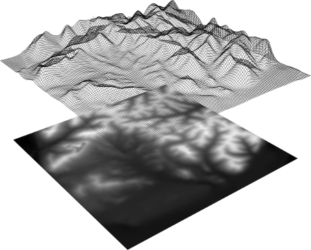
An example heightmap (1)
A heightmap is a gray scale image that is used to vary the height of a surface. If you have a surface defined in the X-Z plane, a value from the image would specify the Y coordinate. It is common to assume that the image values are percentages of some specified maximum height. A pixel in an image is typically stored as an RGB (red, green, blue) value, and gray-scale colors have equal amounts of red, green, and blue. Therefore the resolution of the heights is dependant on the number of bits used to represent the pixel component values. Eight bits per component is the common bit-depth, so a typical gray scale image allows for 256 (28) possible height values.
Heightmaps can be used in two different ways. If you have a plane that is subdivided into quads (4-sided polygons), a vertex shader could change each vertex’s “height” using a value from a heightmap. If your model’s faces are not subdivided, then you could implement pre-processing functions to subdivide the faces and use a value from the heightmap for the “height” values. For any arbitrary surface, we would typically take “height” to mean a distance in the direction of the surface normal.
A variation on heightmaps is a displacement map, which changes the location of a vertex along its normal vector. Displacement maps can be used in vertex shaders to modify the geometry of a model as it is being rendered. A displacement map image contains gray-scale values between 0.0 (black) and 1.0 (white). These can be treated as percentages of displacement, assuming you have defined a maximum displacement. To allow for motion along a vector in the opposite direction of the normal vector the percentages can be converted to the range -1.0 and 1.0 using color*2.0 - 1.0. Displacement maps can also be used in fragment shaders to offset the location of a fragment before lighting calculations are performed. This does not change the fragment location in the final image, but it can change the color assigned to the fragment and give the illusion of a rough surface.
Bump map / Normal maps
A bump map simulates bumps on a surface by changing the direction of a fragment’s normal vector based on a bump map image. Changing the normal vector changes the percentage of diffuse and specular light that is reflected off of the surface at the fragment’s location.
The general idea goes like this:
- Each vertex of a triangle has a normal vector. The vertex shader puts the normal vector into a varying variable and each fragment gets an interpolated normal vector.
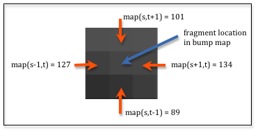
- The fragment shader performs a lookup on the bump map image for the four surrounding pixels of the fragment’s location in the bump map. By calculating the difference between the values in the horizontal and vertical directions you get the amount of relative change around that location. (In mathematics this is called a “finite difference” method.) The diagram shows 9 pixels in an enlarged area of an image where the difference between the horizontal pixels is 7 (134-127) and the difference between the vertical pixels is 12 (101-89). This gives us a perturbation vector to modify the surface normal vector. In the diagram’s example the perturbation vector is <7,12>.
- The surface normal vector is modified by the finite difference calculated from the bump map.
- The diffuse and specular reflection calculations are performed using the new normal vector.
The perturbation vector needs to be orthogonal to the normal vector to perform accurate bump mapping, but we will leave out those details. The basic idea of bump mapping is to modify the surface normal so that the lighting calculations simulate an irregular surface.
You can think of a normal map as a variation on bump maps. The values in a normal map are not used to modify the normal vector - they are the normal vector! The RGB value of a pixel in a normal map image is used as the <dx,dy,dz> values of a surface normal at that point on the surface. The normal map is defined in the X-Y plane with the +Z axis being the general direction of the surface normal. Since the color (0,0,1) is blue, normal map images tend to be “blueish” in color, as in the example.
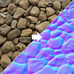
An image and its associated normal map (2)
Because color values in an image are all positive values between 0.0 and 1.0, and normal vectors can point in any direction, the normal vectors have to be transformed before they can be stored in an image. Given a component value of a vector in the range -1.0 to 1.0, it is scale by 1/2 and then offset by 1/2 to get it in the range 0.0 to 1.0 (e.g, delta*0.5 + 0.5). When a color is extracted from the image, each component must be converted back into a normal vector value by undoing the transformation, component*2.0 - 1.0.
It is non-trivial to create normal maps and so they are typically created using software tools. Blender contains tools to create normal maps and save them as images. The term “baking” is often used for this process. The software basically creates all of the normal vectors you want for a particular model and then saves them for later use. That way the work of creating the normal vectors does not have to be repeated.
A parallax mapping is an enhancement to bump maps or normal maps that modifies the texture coordinates at a fragment to provide greater realism and more illusion of depth.
Glossary
- table lookup
- Given a table of values and indexes that specify a location in the table, return the value in the table at the specified location.
- mapping
- Given inputs, return an output.
- heightmap
- Use a value from an image as the “height” of a vertex.
- displacement map
- Use a value from an image to offset the location of a vertex or fragment along it’s normal vector.
- bump map
- Use a value from an image to shift the direction of a fragment’s normal vector which modifies the amount of light it reflects.
- normal map
- Use a value from an image as the normal vector for a fragment.